Originally Published in Issue 31 of 4Low Magazine
Make sure to subscribe to get the newest issues of 4Low Magazine right to your mailbox. CLICK HERE
By Christian Sturtz, [email protected]
Photos by Christian Sturtz
Axle shafts take a beating when you add larger tires, more horsepower, and harder trails. This additional abuse can lead to axle shaft breakage or failure, which could ruin your day. Depending on where the axle breaks or axle design, the wheel could fall off the vehicle. If the axle breaks or strips out at the splines it could damage the differential, ring/pinion, and bearings. While there are many other possibilities, these are a just few examples of the failures you could face.
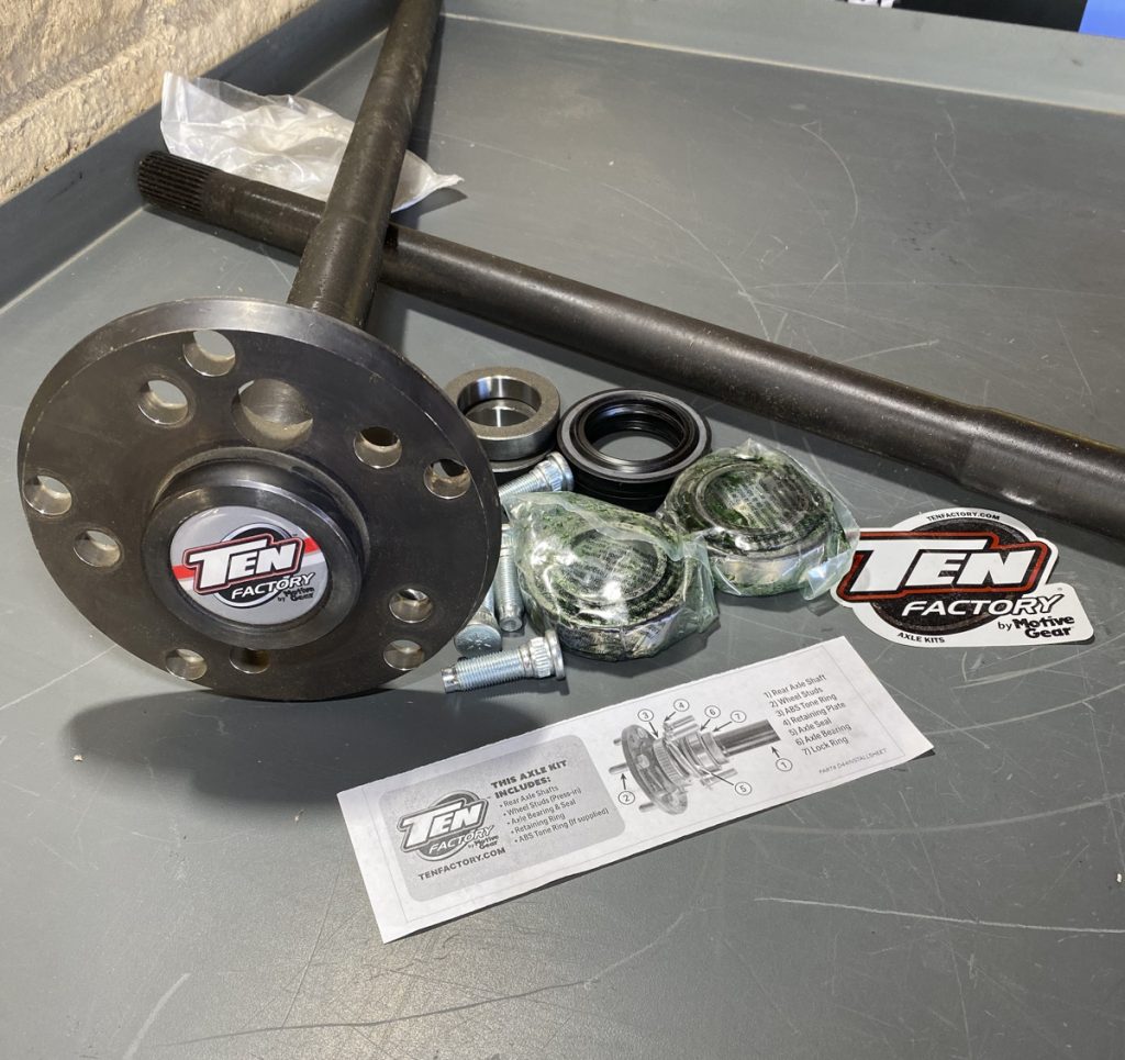
In this article, we set out to cover the removal of the original equipment (OE) shafts and install stronger 4140 alloy shafts on the rear of a 2005 Jeep LJ. Most OE shafts are a 1040 alloy, with some using a stronger carbon content- 1050 alloy. The 1040 alloy is induction hardened, easily machined, and is known for having a great balance between being flexible and strong. That being said, 1040 and the even stronger 1050 alloy have their limitations. This Jeep is equipped with a Dana 44, which is the stronger of the two axles offered in Jeep Wranglers. The 4140 is a harder alloy, more shock resistant, and less likely to corrode then 1040 alloy. 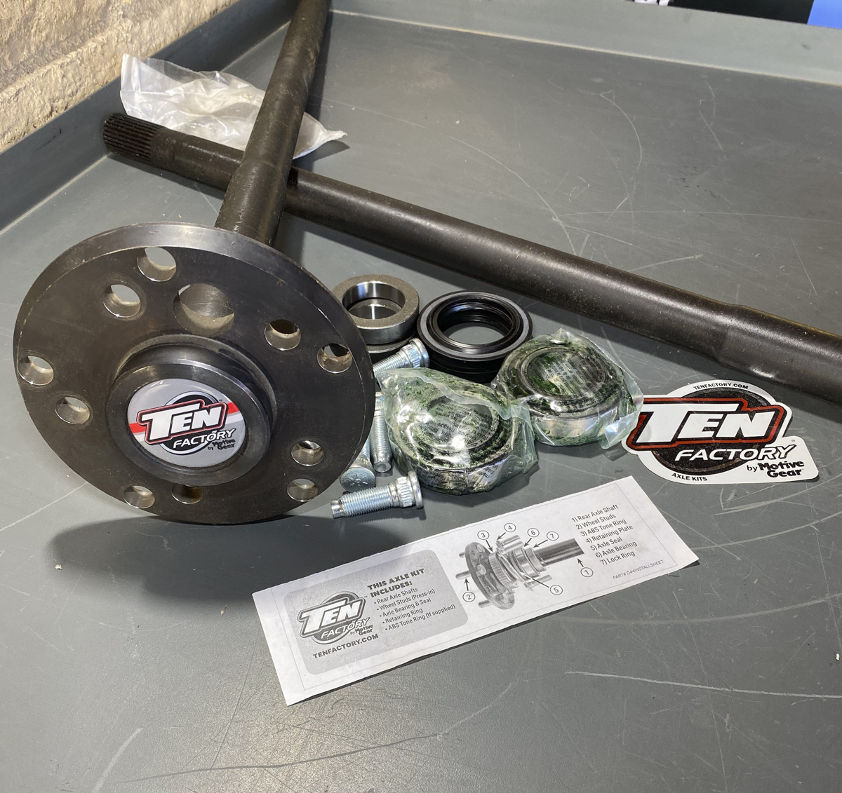 This type of axle/bearing setup is known as “semi-float.” This job, like many jobs on 4x4s, turned into a lot more work then just changing axle shafts!
To start the install we elevate the vehicle, remove the rear tires, and drain the differential. Removing the cover is not completely necessary. However, this is what led us to all of the additional work. We drained and removed the differential cover to inspect the condition of the ring/pinion and differential. If you chose not to remove the cover you may position one end of the axle higher (1-2”) then the other side. Start with the higher side, as this will eliminate most of the gear oil from running out. After you get one side done you would reposition the axle with the opposite end higher and do that side. The calipers and rotors were next removed. “S” hooks are a great way to hold up the calipers.
Next, the axle shaft retainers were unbolted. There is a hole through the axle flange that lines up with these nuts. It will be necessary to place the transmission or transfer case in neutral to be able to turn the axle shaft and line these up. After the 4 nuts were removed, a slide hammer is used to remove the shafts from the housing. Either way you go, with the one side at a time method or if you drain the housing completely, it is normal for some gear oil to run out of the tube.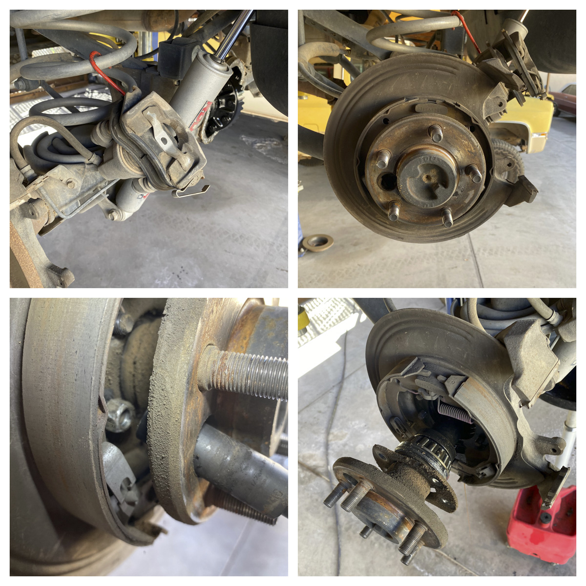
We then set the removed shafts from both sides off to the side to begin inspecting the differential. Right away we saw a few things that needed attention and led us to further explore the condition of the differential. First, we noticed that the carrier caps were flipped over and placed on the wrong sides. This is a sure-tell sign someone has had at least part of this axle apart and didn’t know what they were doing. Spicer/Dana marks the differential cover face and the bearing cap for that side with corresponding letter marks, in this instance the axle was marked with an “A.” The driver’s side face was marked above the centerline with a vertical “A.” The cap next to it should have had the same vertical “A,” above the centerline. It did not. Instead, it was a horizontal “A” rotated to the right below the centerline. When the caps are not positioned correctly it can cause bearing damage, because it creates uneven pressure on the bearings since the journal is no longer round. Differential bearing caps are similar to engine main bearings or rod bearing caps, they have one place and orientation. If you are taking a housing apart that is not Spicer/Dana be sure to mark the caps. Second, we noticed that the preload/adjustment shim had slid out on the driver’s side. If you look at it compared to the passenger side, you can see the difference in Figure 3.
At this point, we decided it would be best to take the carrier and pinion out and check the condition of the bearings and all other parts. We started this by removing the bearing caps from both sides and prying the carrier out. This normally takes a fair amount of effort, however this one almost fell out, which is a sign of worn bearings or incorrect setup. It is important to mark the preload/adjusting shims and bearing races side to side. Some carriers have shims that are under the pressed on bearings and you wouldn’t have to worry about marking them until the bearings are pulled off. An easy way to mark them is with zip ties. The driveshaft was then unbolted from the axle side, the pinion nut was removed, and yoke was pulled off.
With the yoke removed the pinion nut was screwed on by hand and the pinion was tapped out. It is important to make sure you have all of the pinion preload shims when you remove the pinion. Next the pinion seal, oil baffle, and outer pinion bearing were removed. 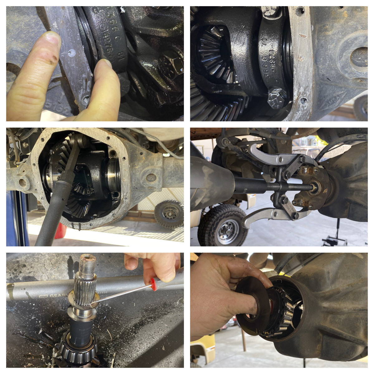
The races were knocked out with an oval punch for better inspection. After looking at the bearing races, both carrier and pinion, we decided the housing at least needed a complete bearing kit. All the races had wear lines and the hard face looked like it was coming apart. The backing plates were slid off, the races were removed from the housing, and the housing was thoroughly cleaned. Cleaning the housing led us to another great find- one of the retainers for the clutches in the limited slip had come apart and got stuck in the oil passage for the pinion bearings. 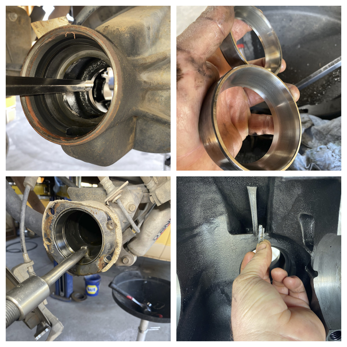
We had future plans to re-gear this axle and install some type of traction device at the same time. With the damaged bearings and differential, it was best to do the upgrade now. It would save time and money by not having to completely take apart the axle twice. For this, we decided to go with a 4.88 gear set and complete master overhaul kit from Motive. The differential is a Select-A-Loc by Auburn Gear. We chose to change the pinion yoke to a stronger u-bolt style, instead of original bolt and strap type. Also the rear cover is going to be replaced with a heavy duty RT Off-road cover by Crown Automotive. It will be all sealed up with a Lube Locker. RT Off-road makes covers for most Jeep applications. 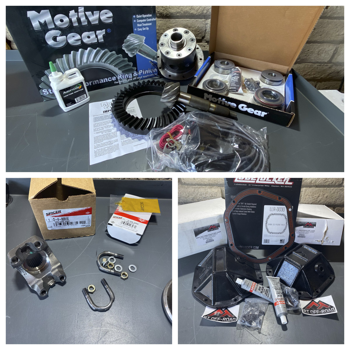
We started the reassembly of the differential by installing the new pinion races. Then, the pinion bearing was removed from the original pinion to get the shim under the bearing. It was measured and placed on the new pinion and the bearing was pressed on. The reason you measure the pinion depth shim is to get a starting point in your head if the pinion depth is not correct. It also is a quick check if the housing or your original ring and pinion are out of spec. Most ring and pinions include a reference guide/spec book that give you correct gear patterns and specs, including pinion starting shim thicknesses. This Dana 44 pinion shim thickness was 0.055” and the recommended starting spec for a Dana 44 is 0.042.” This is a 0.013 difference then the recommended starting spec, but is fairly normal. If it was 0.020” or more different than the spec you may have an issue with: the ring and pinion, the housing is out of spec, or it was set up wrong. This may lead to a little more challenging setup.
A light coat of grease was applied to the pinion bearings. The outer bearing and baffle were installed into the front of the housing and the seal was drove in. Then the pinion was slid in the back of the housing with the original shims, yoke was slid on, and pinion nut was torqued to spec. With the original preload shim thickness the preload was not enough. We removed a 0.002” shim and it gave us the correct amount of preload, 14-19 in-lbs of drag. It is always a good idea to apply a little thread lock to the threads of the nut and silicone sealant to the back of the nut to prevent gear oil leaking through the splines. 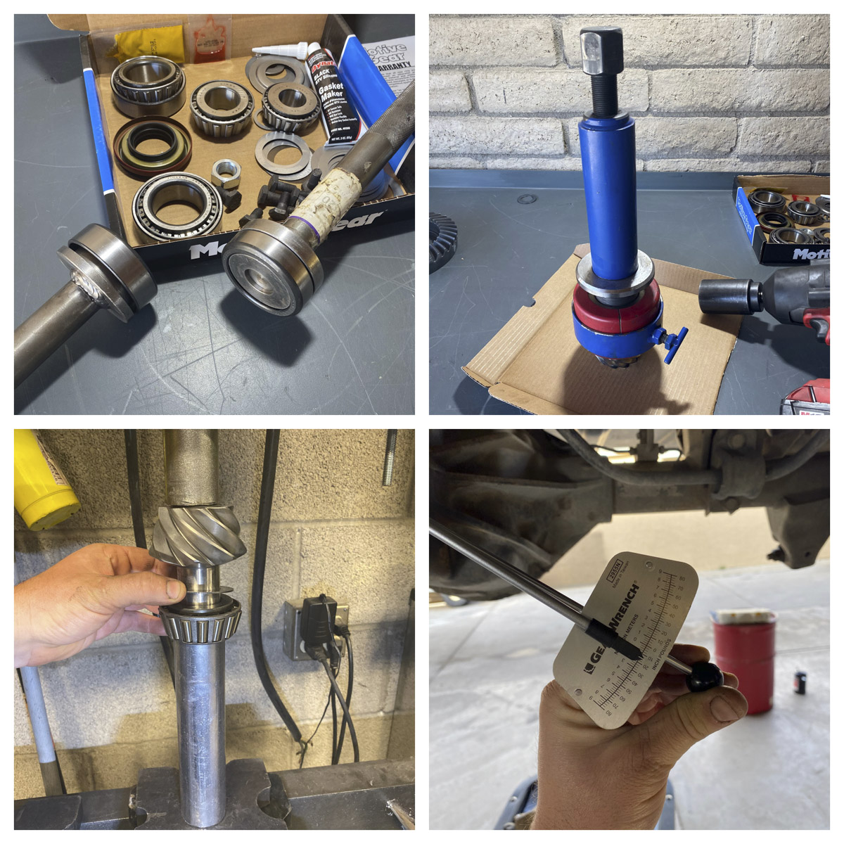
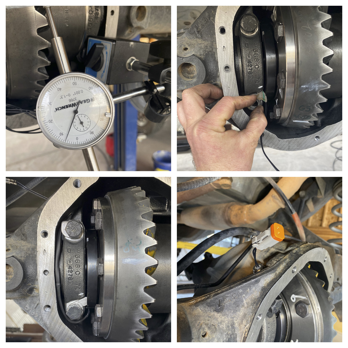
To install the electric locker a hole was drilled, tapped to ½” x 20 for the fitting, and the lower part of the fitting was installed into the housing for wires to run through. Then, the new ring gear was bolted to the carrier and torqued in a criss-cross pattern, in steps to the spec. The carrier bearings were pressed on and coated lightly with grease. Then the carrier was installed in the housing with the original shims. It is important to use a case spreader and/or shim drivers to tap the shims in evenly. The original shims were close but it had no preload or enough backlash (clearance between the ring/pinion). So we needed to increase the amount of shims to get some preload and get the ring and pinion further apart to get some backlash. We added shims to the passenger side. After a few tries we ended up with the original thickness shim on the driver’s side and 0.013” more on the passenger’s side. The caps were torqued; backlash was checked at 4 different places on the ring gear. Spec for this axle is 6-10 thousandths and we were at 8 thousandths, so it was within spec. Then, the contact pattern was checked with marking compound and the lock for the electro magnet was fit. We used the optional additional lock to help hold the wires out of the way; the caps on that side were then re-torqued. We installed heat shrink on the wire for protection. The wires were fed through the housing, the top/compression part of the fitting was installed, and the plug-in was assembled. 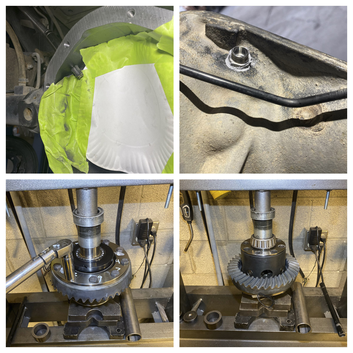
The heavy-duty cover was installed and sealed with a Lube Locker. The Select-A-Loc has very simple wiring directions. The hardest part is figuring out where you want to place the switch. There are several aftermarket companies that make compatible switches, if you don’t want to cut any holes. Be sure to carefully route wires so they are away from any heat source and moving parts. 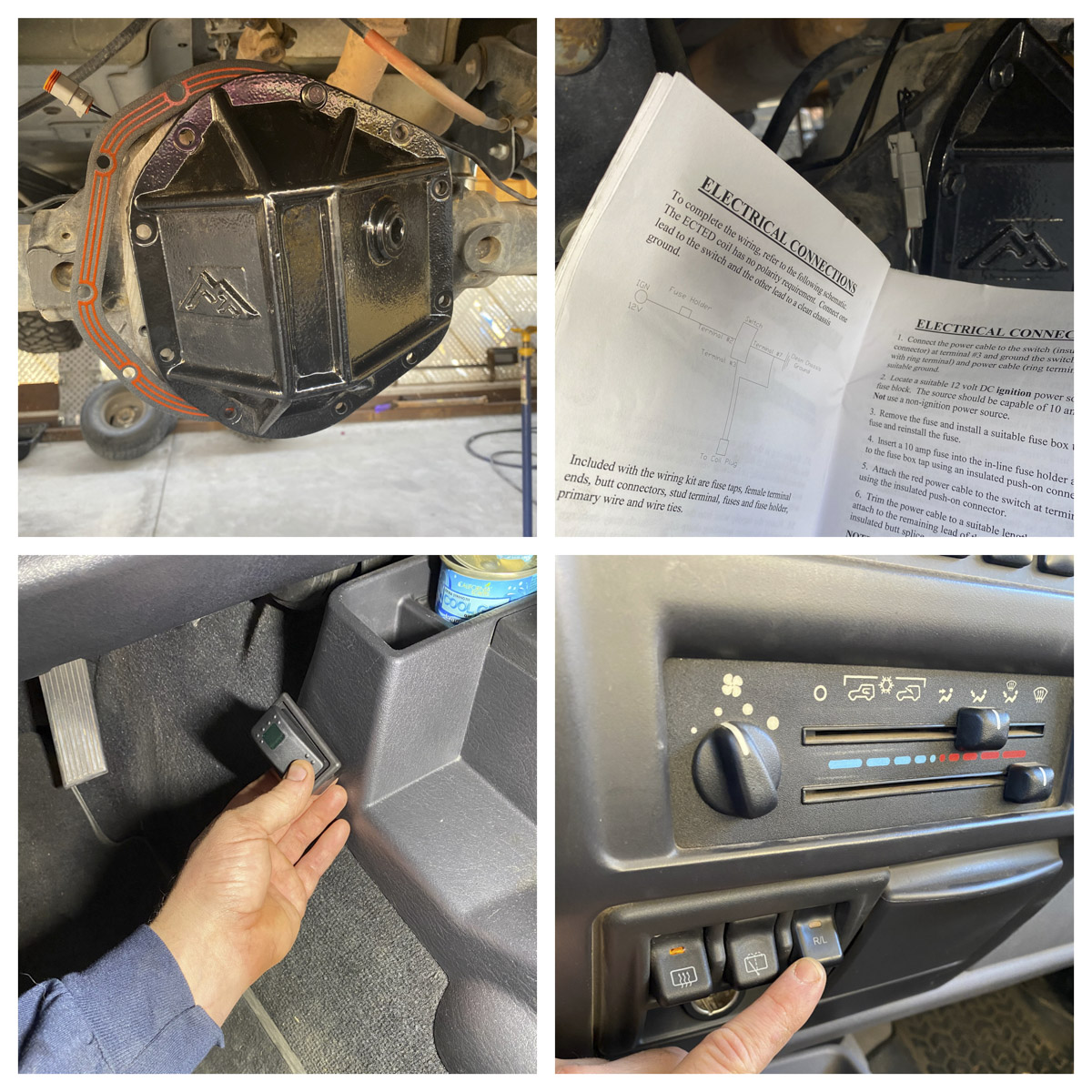
Finally! To get back to our original task, installing the 4140 alloy shafts. Instead of cutting and pulling off the old bearings to get the original axle retainers- we got new ones. There are two different retainers, one for disk and one for drums so, be sure to use the correct one. The wheel studs are pressed into the axle flanges. It may be necessary to use longer wheel studs if your wheels are thick; a good Napa part # for longer studs that work is 641-4222. The retainer and seal were slid on and the bearing was pressed onto the axle. Finally the bearing retainer is pressed on. It is common for some shards to come off the axle/retainers when pressing them on. Make sure and remove the shards before installing the axle into the housing. Bearing retainers sometimes have a more pronounced taper on one inside edge than the other. If so, put that side on the axle first, it will press on easier this way.
Reassemble the axles and brakes in the reverse order they were taken apart. One additional feature the Motive axles have is that that they are duel drilled for stock pattern and 5 on 5 ½” pattern, on this application. We had a local machine shop drill out new rotors to the larger pattern and also replaced the brake pads. The RT covers, like many aftermarket covers, have a higher than original fill hole. Do not fill to this level or the axle will be way overfilled! We added the supplied limited slip additive then used a bent zip tie (compared to the original cover) to gauge the correct gear oil level. 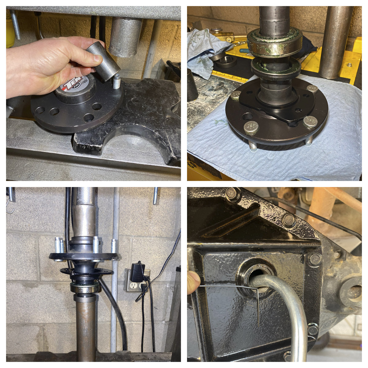
Part Numbers Used:
Motive Gear
- Axles Shaft Kit (MG22135)
- Master Overhaul Kit (RA28LRMKT)
- Gear Set (D44-488GX)
Auburn Gear
- Select-A-Loc Differential (545018)
Lube Locker
- Diff Seal (LLR-D044)
Napa
- Rotor (48880134)
- Pads (ss-7863-x)
- Wheel Studs (641-4222)
Spicer
- Yoke (2-4-8091x)
- U-bolt kit (2-94-28x)
- Oil Seal Retainer Disc (51762)
- Oil Sea Retainer Drum (47160)
Sources:
Motive Gear
1001 W. Exchange Ave.
Chicago, IL 60609
800-934-2727
www.motivegear.com
Napa
800-538-2672
www.napaonline.com
Auburn Gear
400 E. Auburn Drive
Auburn, IN 46706-3499
260-925-3200
www.auburngear.com
Spicer Parts
3939 Technology Drive
Maumee, OH 43537-9194
800-621-8084
www.spicerparts.com
Lube Locker
37 Enterprise Way
Dayton, NV 89403
www.lubelocker.com
