Builds, Product Highlight
8 POINT GREATER
By Christian Sturtz, [email protected]
Photos by Christian Sturtz
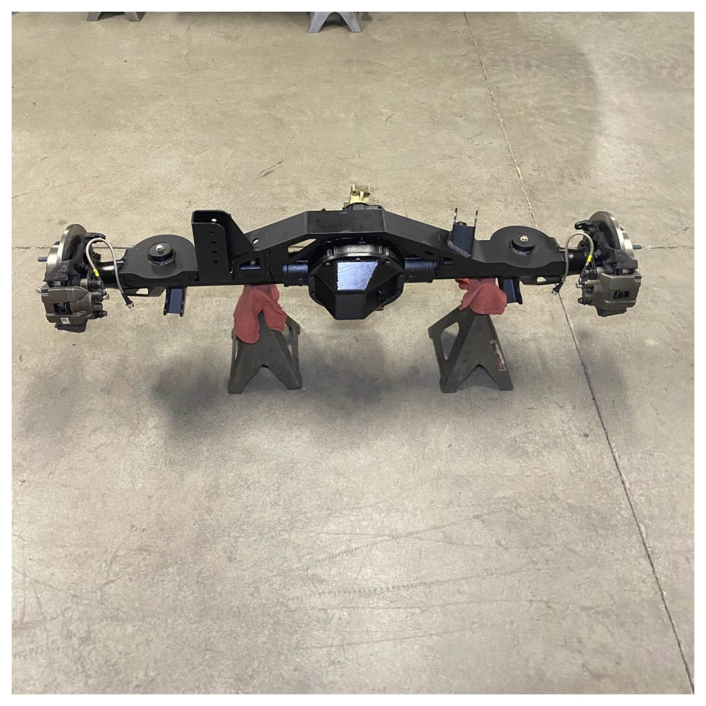
 In Issue 36, we showed you how to install a Barnes 4WD axle bracket kit on a Ford 8.8 differential. Here, we are going to show you how to make that 8.8 even greater. First, we need to mount the axle and check for clearance, set shock mounts up, and completely weld axle brackets. We will also cover the brief install of 4.88 gears, new bearings, a Grizzly locker, and a C-clip eliminator kit. To finish it off, we will seal it up with a Lube Locker and cover it up with a heavy-duty cover from Revolution Gear and Axle.
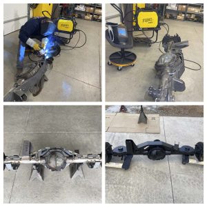
The Barnes bracket kit’s instructions instruct you to mount the axle and cycle the suspension to check for clearance issues before welding. You should also cycle the suspension to get the shocks in the correct location. We started by bolting the axle in position without the coil springs in place. Then, we adjusted the axle to full droop (i.e., shocks line up with the axle and are fully extended). We measured over from the backing plate to our desired location and tacked the shock mounts into place. Next, we cycled the suspension and checked for clearance everywhere. The only places we had clearance issues were the exhaust on the passenger side and the top of the track bar on the driver side at full compression. The exhaust could be lengthened in one area to eliminate this contact.
The track bar mount on this axle kit is very tall and has a lot of adjustments available (i.e., holes). We chose to run it on the second hole down from the top and cut off the first hole area. Also, make sure your shocks and bump stops are bottoming out at the same time or your bump stops bottom out just before your shocks. If not, adjust your bump stops or shock mounts accordingly. Finally, we removed the axle to weld it fully. Keep moving while welding, so you don’t create too much heat in one area; the instructions included with the Barnes axle bracket kit also go over this. 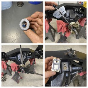
To start the ring and pinion install, we removed: the cover, center pin bolt, center pin and rolled the spider gears out. The axles were pushed in, the c-clips were removed, and the axle shafts were removed. The side gears can then be slid out of their journals in the carrier. Then we marked the carrier bearing caps and removed them. Next, the carrier was pried out, and the shims from both sides of the bearings were marked with zip ties. Finally, we loosened the pinion nut, and the pinion tapped out.
The pinion seal was removed with a pry bar. Don’t get too carried away with the pry bar; it is easy to gouge the seal surface. Also, make sure to keep the slinger that goes behind the pinion seal; you will reuse it later. We used an oval punch to knock out the pinion races. The 8.8 axle shims are under the inner pinion bearing, but you should always look for shims under the bearing races. Next, we knocked out the axle shaft bearings and seals. Finally, we cleaned out the axle housing.
With the housing bare and clean, it was time to start putting it back together. We started by driving the pinion bearing races into the housing with some Yukon drivers. The drivers, with their precision fit and design, make this an easy job. Then we de-burred the ring and pinion and started the ring gear bolts through the carrier. Rinse the bolts and the holes in the ring gear with brake cleaner because both come with oil on them. Also, use red thread lock on the ring gear bolts. We decided not to reinstall the ABS tone wheel as it’s not needed in our application. Next, the ring gear was tapped down with a rubber mallet, and the carrier was placed in the press to hold it while the bolts were tightened and torqued. We also number the bolts in a crisscross pattern, so they get tightened equally. Finally, the bearings are pressed onto the carrier. If we were not using this Grizzly locker and not getting rid of the c-clips, it would be necessary to notch the ring gear to remove the center pin. We removed the center pin retaining bolt to check out the design, then reinstalled it with thread lock and tightened it.
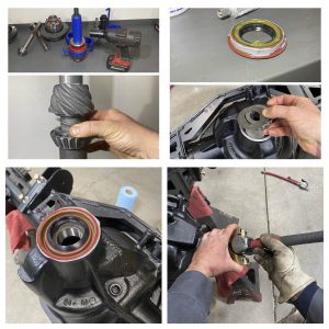 On to the pinion gear and its setup. We started by pulling the bearing off the original pinion to get our starting shim. The shim was close to the starting spec, so we cleaned it up, put it on the new pinion, and pressed the bearing on. We greased the carrier bearings and the pinion bearings lightly, and the new crush sleeve was slid onto the pinion. Next, the back of the new seal was packed with grease to hold the spring in position while driving it in. The outside of the seal was lightly coated with silicone sealant. The bearing and slinger were dropped into position, and the seal was driven in. Finally, the pinion was slid into the housing and, with somebody holding the pinion, the yoke was tapped on.
It’s always a good idea to put thread lock on the pinion nut and silicone sealant on the back of the nut.
To set the pinion preload, start by slowly tightening the nut. You want to first tighten the nut until there is no endplay on the yoke. Then you tighten a little more until you achieve the pinion preload spec. Sometimes these crush sleeves are very tough and require you to use a yoke holding tool. We then installed an ABS block-off plate from Iron Rock Off-Road.
Now the carrier is ready to be dropped in. We started by making up shim packs that were the same thickness as the originals. Then we dropped the carrier in, drove the shim packs in, and tried it. It felt like it had enough carrier-bearing preload, but we had too much backlash. So, we moved a .005″ shim from the non-ring gear side to the ring gear side to decrease backlash. Next, the backlash was checked with the magnetic dial indicator. It was right within spec. .006 – .010″. We double-checked the torque on the carrier bolts. Finally, the pattern was checked with marking compound; the Lube Locker and Revolution cover were installed. 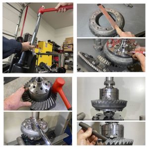
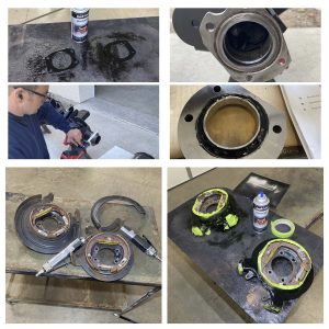
The only thing left to do is the axle shafts. We painted the retainer plates, and while those dried, we modified the bearing ends of the housing. We started by stuffing rags just inside the axle tubes and cutting the original bearing area off, per Yukon’s instructions. After both sides were cut off, de-burred, and cleaned up, the rags were removed. The lip on the new bearing retainer blocks was filled with silicone and pulled into position with supplied bolts. Our axle came from a salvage yard, and the backing plates were pretty hammered. So, we cut part of the dust shield off our brake backing plates. Finally, we painted the backing plates.
The axles have dual pattern wheel studs. We chose the 5 on 5.5 pattern. The wheel studs are bolted through the axle flange, and when installing, we used red thread lock on the base of the wheel studs. Then the axles are assembled and pressed together. We always press the retaining ring on separately; this ensures complete seating of the bearings. Then the correct backing plate is slid onto the bolts. Next, a thin coat of silicone sealant is applied to the sealing area. The axle retaining plates are tightened equally, in a crisscross pattern, and torqued. Finally, the brakes are installed. Changing the bolt pattern on our axles require that our rotors be re-drilled at a local machine shop. Now you have a greater 8.8! 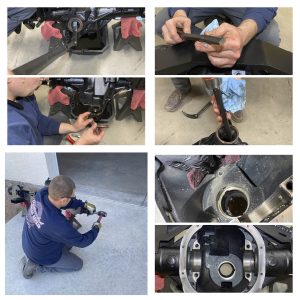
Parts Used:
Yukon Gear and Axle:
Yoke (YY F880622)
4.88 Gears (YG F8.8-488)
Bearing Kit (YK F8.8-A)
Grizzly Locker (YG LF8.8-31)
Axle Kit (YA WF88-31-KIT)
Iron Rock Off Road:
ABS Block Off Plate (10115)
Revolution Gear and Axle:
Diff Cover (40-2013)
Napa:
2- Rotors (4886565)
Pads (AD-7758)
Tools Used:
Yukon Gear and Axle:
Race Drivers (YT BDM802011) and (YT BDM88010)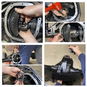
Shim Driver (YT SD-01)
Yoke Holder (YT YH-01)
ESAB Welding and Cutting Products:
Rebel (EMP 205ic)
Sources:
Yukon Gear and Axle
10411 Airport Rd.
Everett, WA 98204
888-905-5044
Iron Rock Off Road, Inc.
12906 Ventura Ct., Suite 6
Shakopee, MN 55379
877-919-5337
Revolution Gear and Axle
16411 Berwyn Rd
Cerritos, CA 90703
844-213-4327
Esab Welding and Cutting Products
Denton, TX 76207
800- ESAB- 123
GEARWRENCH
APEX Tool Group
910 Ridgebrook Rd. (Suite 200)
Sparks, MD 21152
1-800-688-8949
